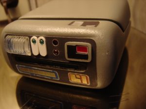
Finishing up the viewscreen
April 3, 2005
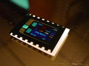
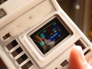
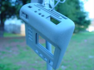
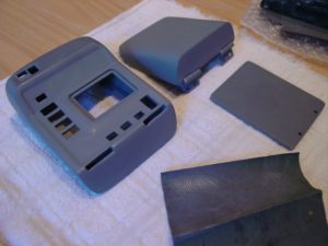
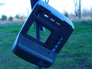
It’s been awhile since I’ve had a chance to work on this, but I had some extra time this weekend, so I’m at it again. Following the splash coat from the previous step, I went over the main parts with some Squadron green putty, designed for smaller gaps, since that was primarily what was revealed by the splashcoat. I was actually very happy with how the body came out following my first coat of paint. I then wetsanded everything again going from 400 to 800 grit paper. Since the cold weather recently returned, I spent today finishing up the viewscreen components and fine tuning the graphics. First off, I cut a sheet of semi-transparent paper to match up with the viewscreen graphic. This sheet will act to diffuse the backlighting that will illuminate the viewscreen. This way, instead of having one concentrated area of light on the graphic, the entire screen will be lit.
I gave both pieces a quick test-fit to make sure they fit into the recess for the viewscreen and aligned properly with the rest of the body.
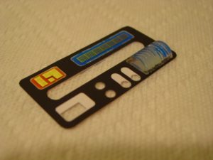
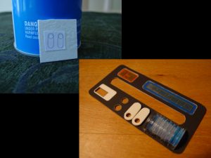
Since everything looked good, I moved on to finishing up the graphics. As I previously mentioned, all the graphics were cut to fit into their respective areas. The only thing left is to add the “greeblies” to the graphics that will go over the top portion of the tricorder. This includes one piece of half-roung acrylic, and two small pieces of styrene. Since I’m lacking styrene, all I got done today was gluing the acrylic round in place.
Primer
April 22, 2005
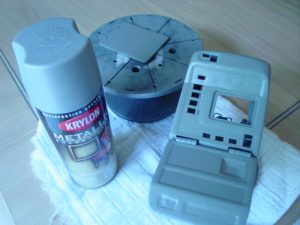
Since I was happy with the body work following the splashcoat, I decided it was time to prime this puppy. So I applied three thin coats of Krylon’s gray primer (#1314) to each of the three components (the body, door, and back panel). Be sure to mask off the ID LED on the lower door before painting!
After the primer had sufficient time to dry, I gently wet-sanded all three parts with 1000-grit sandpaper to remove any roughness or minor imperfections from the primer coat.
Once the parts had a chance to dry from wet-sanding, it was time for the basecoat of paint. Trying to stay true to the original Next Generation props, I started with three light coats of Krylon’s Stone Gray Gloss (#1605). Again, be sure to allow sufficient drying time in between coats, and be sure to let it dry fully before handling, otherwise you’ll wind up with fingerprints all over the place.
More detailing
May 6, 2005
I finally was able to get some styrene, so I decided to finish up the detailing on the top array decal. I used some spray adhesive to glue the supplied template to a piece of 0.040″ thick styrene. After the adhesive dried, I cut each piece out with my Dremel, and used a combination of 400 grit sandpaper and the dremel sanding wheel to round the edges. Lastly, I used a small drill bit to make a pilot hole in each piece. I then glued the pieces of styrene to the decal with some superglue. After it dried (which took a whole 10 seconds) I used a hobby knife to enlarge each hole until it was large enough to fit the LED that will protrude through it following the installation of the electronics.
Following the previous paint coat, I gently wet-sanded the three main components with 2000 grit sandpaper. This helps remove any minor imperfections in the paint. In addition, it helps give the piece an overall smoothness. Be sure to go very easy at this step as different paints can tolerate different amounts of sanding. This Krylon paint seemed to stand up pretty well, but all paints are different. Be especially careful around edges as they are the most common areas that are easily sanded through. Once the piece had sufficient time to dry, I added a mist of Krylon’s Dull Aluminum (#1403). From the information I’ve seen, this is the same technique used to paint the original props for The Next Generation. I pieced the tricorder parts together so that common surfaces would have consistent amounts of the misted paint. For example, I added this light mist of paint with the tricorder closed and then with it open. This gave all the outer surfaces a common level of the dull aluminum. Also, the surfaces where the decals will be placed also have a common amount of the dull aluminum paint.
Painting some details
May 15, 2005
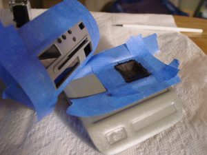
My next step was to add some minor paint detailing to the tricorder. I needed to paint the raised area on the top of the main body that outlines the main grouping of sequencing LEDs. I had noticed previously, that with the graphics in place, you can still see some of the inside surfaces of the LED holes. I decided to paint all the LED holes as well to create an outlining effect when the circuit boards are installed. I used Testor’s flat black enamel, and masked off the areas with Scotch’s blue masking tape (very good stuff for props!). I also painted the area on the lower door for the emergency button. Again, I used Testor’s flat black, and I also used Testor’s flat red for the button area.
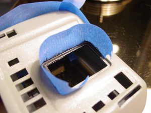
In addition, the outlining rim of the main viewscreen was outlined in flat black as well. The flat finish of the paint doesn’t really matter at this point as I plan on clear-coating everything later. The clear-coat will determine the overall finish of the piece.
Lots of assembling
August 2, 2005
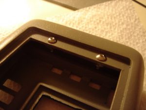
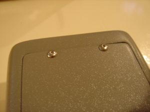
Next, I took the supplied nuts to secure the back access panel. I placed the nuts inside the main cavity and screwed them down using the included screws. I then carefully applied a bead of 5-minute epoxy around the base of the nuts to secure them to the tricorder body. Be very careful as not to epoxy the screws or else you’ll never get them out.
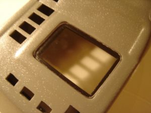
I then moved onto installing the clear plastic piece that would serve as the display screen. While I had sanded down the piece for a tight fit prior, the additional thickness of the coats of paint required some additional work to get the piece to fit in the recess. However, the final fit was so tight that this piece didn’t require any additional adhesive.
Onto the fun part; it was time to attach the lower flip-out door to the main body. By inserting the hinges into their respective cut-outs, you can use some epoxy or hot glue to affix the hinges to the inner portion of the main body. Be extra careful not to get any adhesive on the hinges otherwise you might go through what I did. I used some epoxy that ended up dripping down over the hinges, rendering them useless. After I pried the two halves of the tricorder apart, I had to tear the hinges off the door. This required the installation of a new set of hinges (including more Bondo, sanding, painting, etc). After I got the new hinges installed and started painting, I noticed the styrene sheet used to close the access panel of the lower door was coming loose. I discovered that during the process of wetsanding the newly installed hinges, water had leaked into the cavity of the lower door through the hole drilled out for the ID LED. The moisture, combined with the heat from outside, weakened the epoxy I used to attach the door. This required that I reattach the door, Bondo, sand, paint, etc….AGAIN. So be very careful when attaching the hinges. And if rework is required, be sure to seal the LED hole with some masking tape.
So after all that, I finally go the lower door and main body put together!
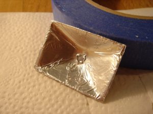
Next, I moved onto installing the “bucket” part of the display screen. This bucket will serve to back-light the film cell used as the display. I used some spray adhesive and tin foil to make sure the inner portion of the “bucket” was very reflective so the light from the LED would be more effective in lighting the film cell.
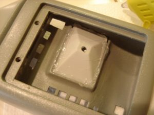
I then placed the pre-cut film cell with diffusion sheet into the recess of the main body. I carefully installed the “bucket” portion on top and held it down firmly to hold the film cell in proper alignment. I then ran a bead of low-temperature hot-glue around the “bucket’s” edge to secure it in place.
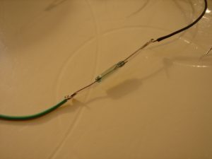
Moving onto the electronics, I soldered the magnetic reed switch I prepared earlier in series with the positive terminal of the battery. When installed in the location I tested before, the magnet will be engaged, causing the switch to be an open circuit. With the switch open, the battery is disconnected from the electronics, and the tricorder will be off, which is what I want. When the door is opened, the magnet is disengaged, the switch becomes a short circuit, connecting the battery to the electronics, and the circuit boards are powered on.
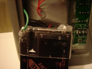
The kit comes with a vacu-formed piece of plastic to hold the J-type battery that powers the electronics. I found it needed a little help to get the wires to make proper contact with the battery terminals. (Basically, I had all the electronics installed only to find out they didn’t work. I spent a couple hours un-installing them only to find out the battery wasn’t making contact with the leads!) I tied the leads from the circuit boards around two spare screws I had laying around the house. I then installed these screws into the battery holder with some low-temp hot glue.
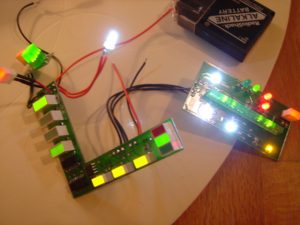
With the battery holder completed I gave the electronics a quick check to make sure they were working properly. Ooo, blinkies!
I moved onto installing the electronics into the main body. Again, I used the low-temp hot-glue as it secures the boards in place very well, but it will not damage the resin body or electronic boards. In addition, if anything does go wrong, the glue can be removed with a little isopropyl alcohol. And it’s cheap! After the boards were installed I gave everything a quick check to make sure everything was still operating and to ensure my reed switch was in the right place.
Time to button up
August 10, 2005
Now that I had the electronics and battery installed, the next step was to seal up the back panel. I had to do some slight arranging inside the main body to get the battery to fit completely inside, but it wasn’t too difficult. Following that , I just used the supplied screws to attach the door. I had to re-tap the holes to get the paint out of the screw holes, but after that, they went right in and lined up nicely with the previously attached nuts.
Next step was applying the graphics. Since all the graphics were precut in an earlier step, I just gave them each a quick test fit to make sure they fit in their position properly. All of them fit just fine, except the graphic for the top array. That’s because the LEDs that go underneath the small styrene greeblies were too large for the holes I had drilled in the styrene. It was an easy fix as I just used my hobby knife to drill out the holes until they were large enough to accommodate the LEDs. After that, each graphic got sprayed with photo-mount spray adhesive then applied. Almost done!
Final details
August 15, 2005
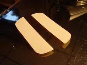
To detail the bottom portion of the tricorder, I first cut a template out of a manila folder. These two pieces will go on the bottom of the main body and flip out door.
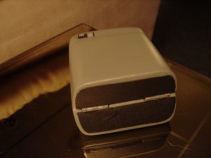
Once the templates were cut out and test fit on the bottom of the body, I used my hobby knife to cut them out of a roll of black gaffer’s tape. I then applied them to the tricorder. All that’s left is the small greeblie on the top array.
Detailing the top graphic
August 17, 2005
As mentioned above, the last step is attaching the small greeblie on the top array. I gave it a quick test fit to make sure it fit over the protruding LED, and it fit fine. The only fit problem was getting the flat piece of resin to sit flush against the rounded surface of the top array. To remedy this problem, I let the resin soak for a few minutes in some hot water. I then gently shaped it around the curvature of the kitchen sink. The curve matched nicely to the curve of the top of the tricorder, so now the piece sits well on the top array. Next up is painting the little bugger.
Well I managed to get the little greeblie painted. I used the exact same paints and methods as I did when painting the body, aside from sanding in between coats. I figured since it was a small piece, the finish was not that important. I also kept the coats light and few (one coat of primer, one coat of gray, one coat of silver) to prevent excessive paint buildup that would prevent the LED from fitting properly in the hole. I then masked off a small square using the edges of the hole as guidelines, and painted the black square using Testor’s flat black. I then sealed it all with 2 light coats of clear. I then applied a small drop of glue to the back and put the piece over the LED.
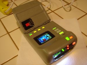
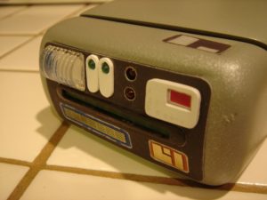
This was the last step for this kit, so the tricorder is now finished! It took a lot longer than I had hoped, but I am pleased with how it came out. Look for a page dedicated to this tricorder on my props page, coming soon!

