Basecoat
April 26, 2006
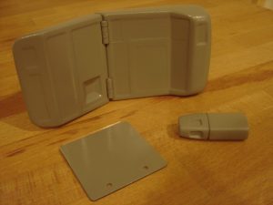
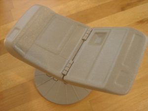
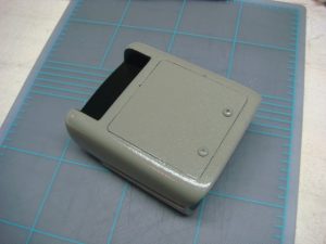
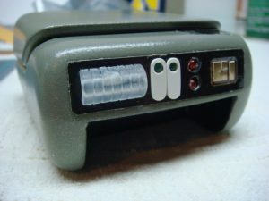
Well again, I managed to sneak some hobby time in amongst the million other things going on. I was able to get the basecoat done. Per the instruction manual, I used Krylon’s Stone Gray Gloss spraypaint (#1605). I was sure to give the tricorder and scanner three good coats on each surface (open, closed, and the back) to ensure no light leakage and ample paint coverage. Just be careful when painting the back. A tip is to paint with the access door in place, but too much paint here will get the panel stuck, so you may need to clean out the gap with a sharp hobby knife after painting.
Misting
May 2, 2006
After the paint dried it was time to apply a misting of silver to the tricorder and scanner. Misting is holding the paint source about two feet away from the subject and applying the paint in short passes. This gives a light coat of the secondary paint. The kit instructions call for Krylon Bright Silver (#1401), but I opted for Krylon’s Dull Aluminum (#1403) since I already had it. Be careful not too apply too much silver, but if you do, it can easily be undone by misting the basecoat back over.
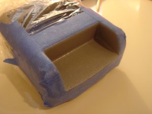
Next, I masked off the scanner pocket and EMRG area on the lower door. Please note that I deviated from the instructions with regard to this step. The instructions call for these areas to be painted black prior to priming. To be honest, I got a little ahead of myself and skipped over that step. Instead, I masked off the areas here and applied Krylon’s Ultra-Flat Black (# ). Whether the paint is gloss or flat really doesn’t have much impact at this step since the overall gloss will be determined by the final clear coat. Also, I would always recommend following the instructions, but it’s important to realize some steps are interchangeable.
Clear Coat
May 13, 2006
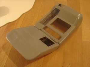
After the black dried, I applied a high gloss clear coat. While most times I use the respective paint brand’s clear coat, I opted to use Dupli-color Automotive clear coat, since I’ve seen it gives a much higher shine than Krylon’s clear. After three good coats and ample drying time, I went in with my hobby knife, and trimmed around all the masked areas and carefully removed the masking tape. Be very careful with this step, as it’s very easy to pull up paint when removing the tape.
Detailing the Scanner
December 28, 2006
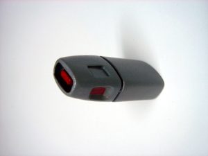
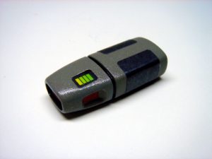
Well after a long hiatus, I’m back at it again. My next step was to detail the small hand scanner. I was lucky enough to come across the owner of the kit used to create the instruction manual for this build (thanks, Mr. Munson!). From the photos I was able to recreate the detailing. I used dark gray and red acrylic paints. First, the recessed area was painted gray, and then the “LED” portion was carefully painted red. I also detailed the side recess using red to simulate a button. The whole thing was finished off with three coats of Dupli-color Automotive clear coat. Next up will be a combination of installing the electronics and applying the decals, so stay tuned!
Finishing up the Scanner
February 2, 2007
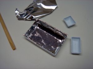
Next up is a toss between installing the electronics or applying the decals. I opted for decals first since the masks I created when painting are positioned to line up with the graphics. It will be much easier to align the electronics to the graphics then it would be to install the electronics and then trying to get the graphics to line up along with covering the bare spots. But in preparation for installing the electronics, I took the three supplied plastic dome-like pieces that are used to surround the electronics to reflect the light. I sprayed them each with some Krylon spray adhesive and attached some aluminum foil. This will help create a more reflective surface for the LEDs.
Using some 400 grit sandpaper, I then scuffed up the areas where the decals will later be applied. I was careful not to sand over any area where the electronics will be as the scratches will be visible. I then used a damp paper towel to wipe off any residual paint and then wiped the whole kit down to dry. I decided to apply the decals to the scanner first. I first gave each decal a quick test fit. I applied the decals using a pair of tweezers and my edged wooden stick. The LED and gray panel decals were easy to apply, but the pin-stripe inside the recess between the two halves took a little bit of fussing, but I got all the decals applied.
Applying the Graphics
March 5, 2007
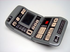
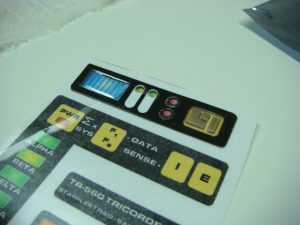
Next, I applied the graphics, minus the one that goes on the top array (more on that later). I used some Krylon spray adhesive to spray the back of the decals. After a few seconds of drying time, I applied the graphics using a pair of tweezers and my edged-stick. For the graphic that surround the display screen, I was also sure to add a bend in the graphic to simulate the angle of the tricorder body. This will help the graphic sit naturally on the kit, without wanting to peal back up.
Detailing the Top Array of Graphics
October 19, 2007
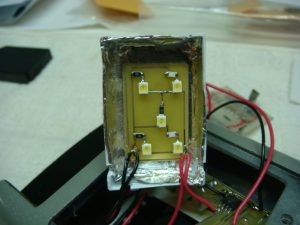
Well another long hiatus over. I’ve actually been working on this, just haven’t posted any updates, so here ya go! So next up was getting the electronics installed. I started with the top array, and carefully got the electronics in place. I found the electronics would not sit flush against the inside of the body, so I opted to drill holes in the top if the tricorder to allow the LEDs to poke through. I then went back in and pushed the LEDs into place, and while I held them steady with a pair of tweezers, I applied some low temperature hot glue to secure them. I then attached the “On” indicator LED by affixing the LEDs to the inside of the tricorder using a spot of super glue. I then went around the LEDs with a bead of hot glue for added support. Next, I attached the display screen LEDs to the dome piece I foiled in an earlier step. Again, I used some glue to attach the board to the dome. I also used a file to make some recesses in the dome for the wires.
Next up was detailing the top array graphics. I used the original set of graphics as a template on where to place the gold leaf detailing. I also did a rough alignment on the tricorder and found I needed to remove some material from around the red LEDs, so I used a sharp hobby knife to scrape away some of the decal’s material.
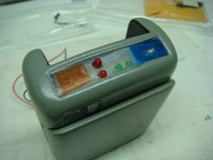
Lastly, I applied the blue and orange gel sheets that were included in my graphics upgrade to the top of the tricorder. Again, I used a set of tweezers and an edged-stick. Next up, I’ll be applying the top array graphics and securing the last bit of electronics. Almost done…
Installing the Electronics
January 12, 2008
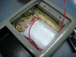
Next up was getting all the internal circuit boards aligned with the graphic windows and then glued down. I found the best way to do this was to align as many windows as I could, and then apply a few dabs of low-temperature hot glue to hold the boards in place. I then flipped the tricorder over and made minor adjustments to ensure the LEDs were lined up as best as they could be. Once I was happy with their placement, I applied some additional glue to secure everything in place. I also took this opportunity to glue down the magnetic reed switch. I did this by closing the lower door and placing the reed in a place that would shut the electronics off. Once I found a good spot, I went ahead and glued down the switch. As you can see, the interior is pretty tight.
My next challenge was getting the battery and battery holder installed. After trying several different ways of situating the battery holder, it became apparent that there was no way I was going to get the battery holder and battery in the cavity and get the back door to sit flush. I ended up removing two of the terminals from the battery holder and soldering the wires directly to them. I then held the applicable terminal against the appropriate battery terminal, and secured them in place with some simple masking tape. It wasn’t pretty, but it got the job done. Carefully, I situated the battery in the back cavity and then attached the back door, which is held in place by two screws. All I have left is some detailing on the upper portion, but I’ll save that for next time…
Finishing Up
January 30, 2008
To finish up the kit, I had to add some details to the upper portion of the tricorder. First was the half-round acrylic rod included with the kit. Since the blue LED was protruding from the body, I had to make a small nitch in the back of the acrylic rod to accommodate the LED. After some work with my dremel, I got the piece to sit flush against the body. I then attached it using some Superglue. The last piece of the puzzle was the two white areas around the blinking green LEDs. The kit does state this, but most of the props I’ve seen had some additional detailing here. I decided to add some 0.040″ thick acrylic sheet. I cut out two small rectangles from some stock acrylic, and then rounded the corners using some 400 grit sandpaper. Next, I drilled a hole in each piece for the green LED to poke through. I then carefully bored out the hole using a sharp Exacto knife until the LED was able to fit properly with the acrylic sheet sitting flush against the body. Both pieces were then attached using some Superglue.
And that about wraps it up. I’m fairly happy with how this kit turned out. It was a very easy build, and the instructions were very nicely laid out. I actually built this as practice for my upcoming Mark VII science and medical tricorder projects, so this one will be going up for sale soon. I’ll also be showcasing it on my prop page. I have a new light tent, so I’m eager to try it out.

