The Mark VII Tricorder Project – Getting Started
November 26, 2004
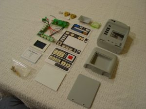
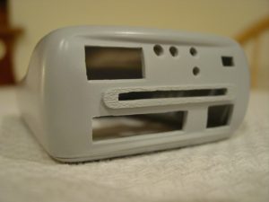
The goal of this project is to construct a replica of the Mark VII Science Tricorder as seen on later seasons of Star Trek: The Next Generation and early seasons of Deep Space Nine and Voyager. Feel free to click on any of the pictures for a larger (pop-up) version. Since I’m not a scratch-builder first, I’ll start off with a kit including the body, graphics, and electronics.
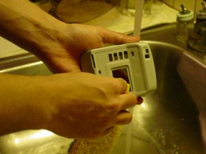
First off, I washed the resin parts in warm, soapy water to help remove any excess releasing agents, which could later interfere with painting. I let the parts soak for a few minutes, then scrubbed with a textured sponge, rinsed, and then let dry.
Body Work
November 27, 2004
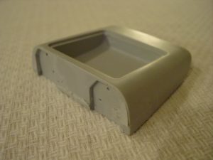
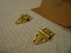
The first thing I’ll tackle is the lower flip-out door. The door will need holes drilled for the hinges, the magnet for the reed switch installed, as well as the ID LED installed, and a styrene panel fitted to cover the LED installation. I began by dry-fitting the hinges in the predesignated recessed areas. Some minor amounts of resin had to be removed for the hinges to sit flush.
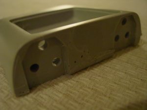
After the hinges fit properly, a 5/32″ drill bit was used to drill the holes for the screws that will secure the hinges.
Since the hinges will later be painted, puttied over, and soldered to, I sanded them both with 220 grit sandpaper to insure the putty, paint and solder will adhere properly.
The Lower Door and Top Array
November 28, 2004
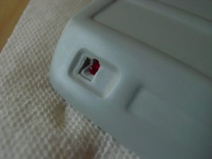
Next, I took the lower flip-out door and carefully drilled a 9/32″ diameter hole for the ID light, which will go in the lower left-hand portion of the door. I then test-fit the LED I will be using to ensure it fit properly.
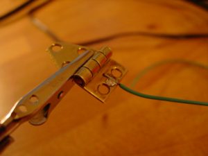
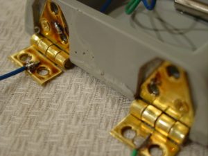
I also soldered two wires to each of the hinges, which will later supply the power to the ID LED in the lower flip-out door. I soldered these wires with the hinges separate from the door since I did not want the excessive heat of the soldering iron to damage the resin door.
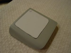
I then measured the dimensions for the flip-out door’s access panel. I cut the provided styrene panel to a slightly larger size than the measured dimensions, then used a Dremel grinding tool to round the corners and remove the excess styrene until the panel fit properly. I also used a small file to remove any excess resin in the door that would interfere with the styrene being attached. I was also sure to mark a common corner on the panel and door so that that panel can be positioned properly when I permanently attach it.
I then filed out the holes for the LEDs on the main body’s top side to make room for the LED array, which will be installed later.
The Reed Switch
December 1, 2004
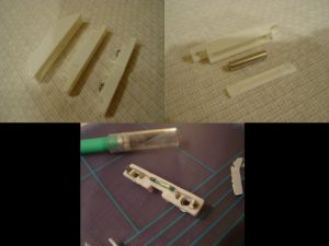
Next I installed the magnetic reed switch that will turn the electronics off and on. The switch is open (the tricorder is off) when the magnet is engaged, or adjacent to the switch. I picked up this one at Radio Shack, part #49-533. You can break the magnet out of its casing pretty easy, but be gentle with the section with the screws as that houses the switch and can break if you bend it. I removed it from the casing by carefully cutting around the edges with an xacto knife. You can then unsolder the switch from the terminals.
Next, I installed the red LED into the lower flip-out door for the ID light. I started by first attaching two wire leads to the LEDs and covering the bare leads with shrink tubing to prevent shorting. I fed these leads through one of the holes drilled for the hinges, and then soldered the leads to the hinges. Again, I soldered to the hinges with them unattached to the door to prevent the heat from damaging the resin.
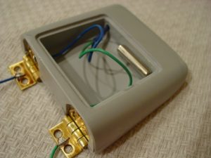
After the hinges had sufficient time to cool I attached them to the lower door using the accompanying screws. To insure a good bond with the resin, I first applied some 5-minute epoxy to the recesses for the hinges, then attached them. This way there are screws and epoxy holding the hinges in place.
Next, I tested the magnetic reed switch to make sure the placement of the magnet and switch will be close enough so that the switch functions properly. I did this by using a digital multimeter to measure the resistance of the switch. I placed the switch is the upper body portion of the tricorder and put the lower door against it to simulate the tricorder being closed. I then put the magnet into the cavity of the lower door and saw that the switch measured open indicating that with the magnet in this position, the tricorder would be off, which is what I wanted. I then used some 5-minute epoxy to secure the magnet in place where I know it will work. *Note: If you don’t have a multimeter, you can hear the switch latch when you put the magnet near it. You can use your ear to make sure the placement of the magnet is sufficient to open and close the switch.
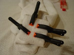
Since all the work in the cavity of the door is completed I decided it was time to button it up. I aligned the panel using the common corner I marked earlier. I then used some more 5-minute epoxy to secure the panel in place. I wrapped the door with a towel and used four small clamps to hold the panel down firmly. I then let it dry overnight.
Bondo
December 12, 2004
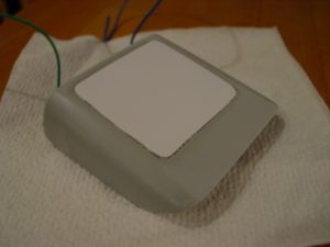
Once the epoxy was cured, I sanded the panel down with 220 grit sandpaper using a circular sanding motion. I also wiped off the excess styrene and resin with a wet sponge in between sandings. I was careful not to sand too tough as to remove the resin of the door itself. I got the styrene panel to be as flush as possible.
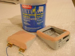
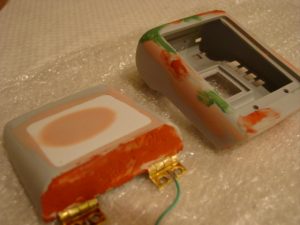
Next, I mixed up some Bondo automotive filler and applied it to the panel and hinges of the lower door, as well as the main seam of the body. Again, I was careful not to put too much Bondo on the hinges, which could later inhibit their movement. I then let it cure overnight just to be sure.
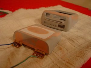
When the Bondo was done curing, I carefully removed any huge clumps with a hobby knife. I also removed the Bondo from the hinge areas, which could prevent the door from opening. I then sanded the lower door on a flat surface, starting with 100 grit sandpaper and gradually working my way up to 400 grit. Again, I used a circular sanding motion, and wiped the door off with a moist sponge in between to remove excess material. I used a sanding block on the hinge-surface to create a flat face.
Putty
January 19, 2005
To finish up the primary body work, I filled any large gaps, holes, or seams with an automotive filler putty that the Bondo may have missed. To fill in the smaller, pin-size holes, I used Squadron’s Green putty. I let the putty dry overnight. The next day I proceeded to wetsand the main body components with 250 grit sandpaper. I then worked my way up to 400, 600, and finally 800 grit paper to ensure a smooth finish on the body. At this point, the body needs a “splash coat” of paint, which will be detailed later. However, due to the wintry weather in my area, this will most likely be put off until the early spring. Until then, I’ll move onto other parts of the kit like dry-fitting the electronics, prepping the decals, and modifying the main body and lower door so they sit flush when the tricorder is closed.
Dry fitting the other components
January 22, 2005
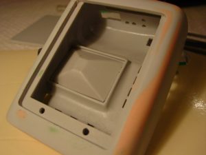
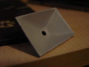
Next up, I dry-fitted the viewscreen’s backing piece to make sure it fit properly into the recess behind the viewscreen. Some minor amounts of excess resin were carefully removed with a sharp xacto blade. As the picture shows, the piece fit with no problems after some minor trimming.
My next step was to test-fit the electronics to make sure they fit properly, and that all the LEDs would fit in their respective places. This required some minor body-work, which I achieved with a sharp blade and some jewelers files.
Lastly, for today, I aligned the lower flip-out door with the main body, so that both pieces sit flush when the tricorder is closed. This was accomplished by removing material from around the hinges so the two pieces would be properly aligned.
Viewscreen
January 23, 2005
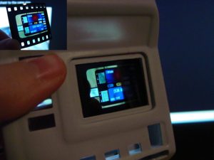
Today, I tackled the top portion of the viewscreen. The screen is composed of three main components; the viewscreen cover, the slide the serves as the viewscreen graphic, and the bucket that goes behind the slide. I took the provided piece that serves as the cover and trimmed it to the red lines on the template using a sharp pair of scissors. I then used my Dremel tool to round the corners and remove any excess material until the piece fit snuggly into the recess of the main body. The process requires minor adjustments; take a little bit off, test fit, and repeat until it fits just right.
Viewscreen prep work
February 4, 2005
Next I drilled a small hole into the back of the viewscreen bucket to allow for the LED that will backlight the viewscreen to fit through. I used a 1/8″ drill to make the hole, and I quickly test-fit the LED to make sure it easily fit through the hole without shorting the two leads.
Then I took the slide that will serve as the display screen and cut it to fit in the viewscreen area. Since the piece already fit width-wise, I simply had to trim the top and bottom portions. I did this a little bit at a time to insure I didn’t remove too much material. It between cuts I test-fit the slide behind the viewscreen area since that’s where it’ll be placed during final assembly.
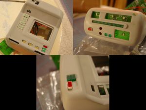
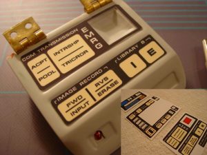
I then started prep work on the graphics. I used a sharp pair of scissors and a sharp hobby knife to cut the graphics apart from the white sheet on which they came. I then test fit each graphic in its respective recess-area on the tricorder body, and carefully trimmed each piece to fit properly. In this picture you can see the lower door’s graphics being test-fitted. Almost looks like a real tricorder doesn’t it?
Splash coat
February 8, 2005
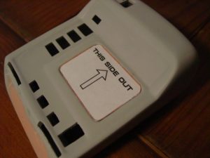
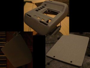
Well I lucked out with the weather and ended up having a warm enough day to get to the splashcoat. For those new to kit building, a splashcoat is a light coat of primer who’s purpose is to reveal any blemishes (seams, holes, cracks, etc) that may be otherwise invisible. Since I plan on using Krylon brand paint for the basecoat, I decided to use Krylon’s gray primer for the splashcoat. Krylon’s primer is good because drying time is quite short. I applied a thin, even coat to the three main pieces (body, door, and back panel) and let them dry overnight.

