The Type II Phaser Project
August 28, 2005
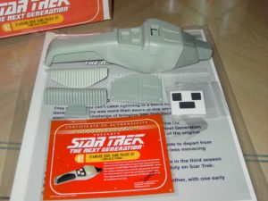
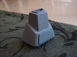
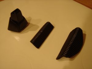
The goal of this project is to construct a replica of the Type II Phaser as seen on later seasons of Star Trek: The Next Generation and early seasons of Deep Space Nine and Voyager. Feel free to click on any of the pictures for a larger (pop-up) version. Since I’m not a scratch-builder first, I’ll start off with a kit including the main components consisting of the body, the emitter, the lower access panel, the setting indicator, and the two grips. If anyone is interesting in building the same kit, you can get one from Roddenberry.com. These kits come right from the people who made the props for the show, so you’ll be hard-pressed to find something better in terms of accuracy. Also, I’ve built up a few of Rodd.com’s kit, and they are of great quality.
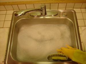
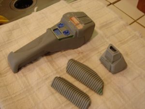
First step, with any cast piece, is to wash it thoroughly. This ensures that any mold-releasing agent present on the kit is removed. This releasing agent could interfere with the adhesion of paint in the later steps, so it’s always a good idea to wash your resin kits before assembly.
Going the Stunt-Version Route
August 29, 2005
It should be noted that the Rodd.com kit includes a very good set of instructions, and if you’re building the standard version of this kit, you should use them. However, I am building what can be considered the “stunt” version of this prop. The main difference being the “hero” version this kit is designed to replicate and the stunt version is the hero has a green indicator meter on the top side of the phaser. I will be filling in this section so that the indicator is not visible. To start, I used 215 grit sandpaper to sand down the indicator piece until it sat just below the surface of the phaser body. This way it can be filled in with Bondo and sanded to sit flush later.
Continuing with the rest of the body preparation, I used more 215 grit paper to sand the bottom portion of the emitter so that the emitter would sit flush against the main body as seen in the picture.
Attaching the Indicator and Lower Panel
August 30, 2005
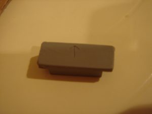
Next I used some 5-minute epoxy to secure the indicator piece in place. Note, that on the Rodd.com kits the indicator pieces are built to fit in one way. If you look on the underside of the piece, you will see a small arrow, as seen in the picture. This arrow should be facing toward the front of the phaser when installed.
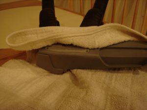
After that I wanted to get the bottom access panel attached. The piece comes with 4 screws that fit into brass fittings cast in the resin. This is a very nice feature since you don’t have to pre-drill or tap anything. However, since I’m doing the stunt version of this piece, I plan on blending the access panel into the rest of the body. When I test-fitted the panel, I noticed the screw heads protruded slightly above the surface of the phaser. I knew this would pose a problem later since you can’t easily sand down a metal screwhead. For that reason I decided just to epoxy the panel on. So I mixed up some more 5-minute epoxy, applied the epoxy, put the panel in place, wrapped the phaser in a towel to prevent scuffing, and used two clamps to hold the panel down tightly.
Puttying over the Indicator
August 31, 2005
More Body Work
September 2, 2005
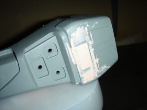
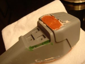
I then used an automotive spot putty and Squadron’s Green Putty to fill in the rest of the gaps throughout the kit. The auto-spot putty is used for larger holes and gaps, while the green putty is designed for smaller holes. The main areas that needed work were around the indicator and the lower access panel. All the Rodd.com kits I’ve built were cast very well and require little body work (that is if you’re building them as they instruct).
Sanding
September 9, 2005
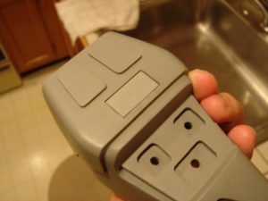
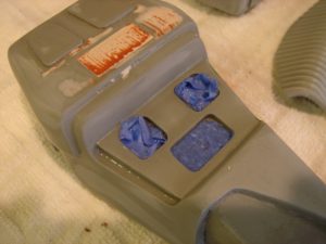
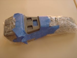
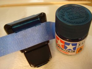
Ok, so now that all the seams, gaps, and holes have been filled in, it’s time to sand. Important note here: Since the body of the phaser has been sealed up, it is very important that you first cover the holes located in the recesses for the buttons. I just used some of Scotch’s blue-masking tape. If you’re building this kit the way it was supposed to be built, you need not worry about this step. However, if you want to built the version I’m building, it is important you cover these holes to keep water from getting into the hollow phaser-body during wet-sanding. You’ll probably never get the water out, and it could have detrimental effects on the access panel and emitter piece that were secured and Bondo-ed over. On my tricorder project I faced a similar problem, and after going through the work of securing, puttying, sanding, and painting, the panel came undone due to the moisture that became trapped in the cavity.
Now it’s time to wet-sand. I usually start with 215 grit sandpaper for the really rough stuff. I then work my way up to 400, then 600, and last 800. Be sure to get in every corner. You may need to use sanding sticks to reach the real tough areas. Also be careful to sand a little lighter around areas you puttied as the putty will sand away much faster than the resin of the phaser.
Once you’re satisfied with the sanding, it’s time for the splash coat. The splash coat is a light coat of primer applied to the piece, which makes any imperfections really stand out. This is good practice as a piece can look very nice after sanding, but once you paint it, you see a lot more of the errors. Using the splash coat prevents having to strip paint and redo your work. For this project I am using Krylon brand paint, so I decided to use Krylon’s primer as most paints are formulated to work best with their own brand. I applied a single light coat to each component of the kit. Once the paint was dry, I went back over looking for more gaps, holes, and such. I filled in any leftover imperfections with more putty and repeated the sanding process. After which, I can apply another splash coat. You can keep repeating this process until you are happy with the body work.
Reshaping the Grips
September 11, 2005
After the primary body work was complete, I gave the two grip sections a test fit. I noticed the upperleft grip did not sit flush against the phaser, so I dunked it in some hot water for a few seconds to soften it up. I then removed it with a towel and held it firmly on the phaser so that it would conform to the shape of the body. I held it in place for a minute or two to allow the resin to cool and harden. Just be careful when using this technique as the resin be very hot after sitting in the warm water.
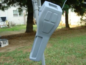
Next up was application of the primer coat. Again, I used Krylon’s Gray Primer (# 1314) and applied three coats to each component of the kit. Be sure to allow ample drying time between coats (about 5 or 10 minutes for Krylon) and sufficient drying time before handling (about 20 minutes). This will help prevent finger prints from being left in the soft paint.
Painting the Accent Pieces
September 19, 2005
Since I was happy with the condition of the emitter and grip sections, I decided to move onto painting them. After the primer dried, I used 1000 grit sandpaper to wet-sand the components. Once they had sufficient time to dry, it was time for the paint. Rodd.com’s instruction call for a gloss black paint. I prefer Krylon, but being I could not locate any in my area, I decided to try a new paint. I went with America’s Finest, which is a type of Rustoleum. The only difference I saw was that American’s Finest dries much faster than your standard Rustoleum (1 hr handling time as opposed to 12 hours for Rustoleum, if memory serves me correctly). The gloss black I used is #HD2879 830. I then gave the emitter and two grip sections three coats each.
Priming the Main Body
October 2, 2005
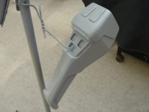
The main body took a bit more body work to get the setting indicator and back panel blended in to where I was happy with it. After that, (as with the other components) I sprayed the main body with three coats of Krylon’s gray primer. Following that, the body got a wet-sanding with 1000 grit paper. Then it was time of three coats of Krylon’s Stone-Gray Gloss (#1605). Similar to my mark vii tricorder kit, I then applied a mist of Krylon’s Dull Aluminum (#1403). I tried to maintain a similar level of coverage as I did on my tricorder since I am planning on display the two pieces as a set.
Since the control panel area needs to be painted black, I used some static wrap and Scotch’s blue masking tape to mask it off. I then gave it three coats of America’s Finest gloss black paint as I did with the emitter and grip sections.
The emitter piece has some extra detailing to add. According to the manual, the small recessed area on the underside of the emitter, as well as the inside of the emitter nozzle itself, gets painted a metallic blue. The manual recommends Tamiya brand paint (#X-13), so that’s what I used. The Tamiya paint is nice because it is acrylic, so any mistake can be undone with some water.
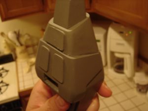
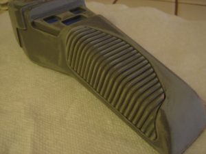
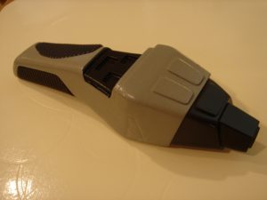
Once the blue paint had dried, it was time to put all the pieces together. Before I did this, I used some rough grit (about 220) sandpaper to scuff the areas for the grips and emitter. This well help the adhesive adhere better. I then mixed up some 5-minute epoxy and secured the two grip sections in place with some clamps. The emitter section was a pretty tight fit, so the combination of that with the epoxy should hold fine. As you can see, it’s almost done. All that’s left are the buttons.
Fabricating the Buttons
October 17, 2005
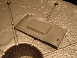
One of the last things to do is to fabricate some buttons for the control pad. The Rodd.com kit comes with a small piece of styrene along with a template to make the buttons. However, I bought this particular kit from a reseller, and the styrene and template were missing. I purchased some 0.125″ thick styrene plastic (as noted on the list of materials in the kit’s instruction manual). I then measured the three hole sizes, and then cut three pieces of styrene to 0.01″ larger than the measured hole. This gave me some extra material to work with for sanding and rounding the corners. I then used 250 grit paper to sand down the buttons until they fit properly. I used a circular sanding motion keeping the button on its side. I’d make a few passes, and then give the button a test fit. Be sure to take your time with this step and not over-do it. It’s easier to sand off more material than it is to try to add it back on. Once I got it so the buttons fit within the dimensions, I then rounded the edges to match the recesses in the control panel. Once I got each button to fit, I labeled them on the back and marked the top left corner. This ensures the button will be installed in the hole for which it was fitted.
Painting for the buttons was the same process as the rest of the kit. I first sanded the button faces down with 400, 600, and finally 800 grip paper, although they probably didn’t need it since the styrene face is pretty smooth. I then gave each piece three coats of Krylon’s Gray Primer. After which, I sanded each piece again with 1000 grit paper to smooth out the primer. I decided to use the Krylon Dull Aluminum paint I had for the trigger button, since the instructions call for a silver or aluminum color paint. Now I just need to find some beige for the other two buttons…

