The Mark VI Tricorder Project
November 21, 2005
Almost a year to the day I started my Mark VII tricorder project, I’m onto the Mark VI. The Mark VI is actually the predecessor to the Mark VII. It was seen on earlier seasons of Star Trek: The Next Generation and featured a less complex top array of LEDs. Instead, the top of the tricorder housed a small, detachable hand-scanner similar to the one seen on the medical tricorder.
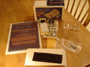
First off, this is another great kit brought to you by Roddenberry.com. Just check under their prop section. This is the 3rd season version of the Mark VI tricorder kit (#1789). The great thing about this kit, is that it was derived from the same masters Ed Mariecki used to create the original props! You can get much closer to the real thing than that. The other major difference between this and Mark VII kit I built is that this kit is vacuformed instead of being resin cast. The nice thing about this is that the body is already very smooth, and it’s clear, so all you need to do for electronics is mask off the appropriate areas…much easier than getting LEDs to align up to holes.
Electronics
December 12, 2005
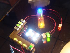
What would a tricorder be without all those blinking lights? Well, in my opinion, very boring. I was fortunate enough to obtain these electronic boards from the same gentleman who made the electronics for the actual Trek series props! He even used the same parts to construct these boards as were used on the the Mark VI tricorders way back when! Needless to say I am very excited to add these to my kit. The electronics also include the magnetic reed switch, which will be used to switch the electronics on and off. Click the picture for a video of the blinkies in action.
Getting Started
December 20, 2005
Magnets
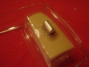
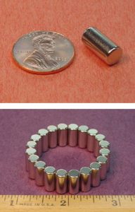
With any kit, you should first read the instructions through in their entirety. This will give you an overall idea of what you have to accomplish and how each step fits in with the next. After reading through the instructions for the kit, I found that one of the final steps is adding a strip of velcro to the detachable handscanner to attach it to the tricorder. I thought I’d try something a little different and decided to use some magnets instead. I went to K&J Magnetics and ordered their D48DIA magnet. I decided to go with this model since it’s small enough to fit inside the scanner (dimensions of 1/4″ x 1/2″). Also, it is diametrically magnetized so the poles are on the sides of the cylinder. This is ideal for my application since the partnered magnet will need to lay flat inside the tricorder housing in order to fit. I gave the two magnets a test fit on the back half of the tricorder body to make sure they’d work. I also marked the touching sides of the magnets so when the pieces are assembled, the opposite poles are touching. This will avoid the magnets from being offset, which would cause them to pull on each other in an attempt to align correctly, which could damage the pieces later.
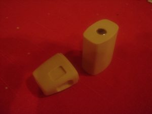
Since the scanner is resin, I first washed the two pieces in warm water and gave them a good scrubbing to remove any mold releasing agent. I then carefully drilled a 1/4″ diameter hole into the lower section of the handscanner. I marked a 1/2″ length on my bit, so I knew where to stop drilling so I wouldn’t put a hole in the bottom of the scanner. The magnet fit in very nicely.
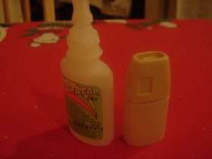
I then used some superglue to secure the two halves of the scanner together.
Once the superglue dried, I placed the scanner in the pocket on the backside of the tricorder body as it will sit when assembled. I then took the other magnet and laid it on the inner side of the tricorder body. This let the magnets naturally align. I then used some 5-minute epoxy to secure the second magnet in place.
Starting the Body Work
December 30, 2005
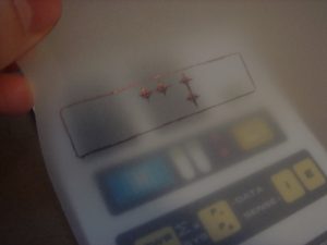
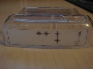
Next step is to drill the holes for the 4 protruding LEDs on the top of the tricorder. To accomplish this, I first checked to make sure the graphics were properly aligned with the LEDs on the circuit board. Once I did that, I used some tracing paper to create a template of the graphic decal that goes on the top portion of the tricorder. I marked the center locations of the 4 LEDs that will stick through the tricorder body. I also outlined the decal itself so I could properly orient it on the tricorder itself.
I then aligned the template in the recess of the tricorder body for the top graphic. I used some Scotch tape to hold the template in place. Note the “Up” note on the tape, which I added to make sure I didn’t put the template on upside down.
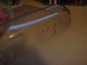
I then used a punch to mark the center of each LED hole. Be sure to use something stiff to back the tricorder when doing this step, as the plastic is very flexible, and using a punch without supporting the material could damage the kit. I then used a 1/8″ drill bit to drill each of the 4 holes. Afterwards, I used a sharp hobby knife to remove the plastic burrs. Last, I gave the circuit board a quick test fit to make sure the LEDs were lined up properly.
Assembly
January 2, 2006
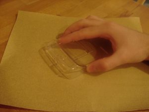
Well it’s a new year and the project continues. Now that the holes for the LEDs are done, it’s time to move on to the primary construction. The first step is to sand all four portions of the body with some 120 grit paper on a flat surface. This will remove any of the major imperfections on, what will become, the bonding surfaces of the different components. I used a gentle circular sanding motion to flatten all the edges, but the kit required very little clean up. Just be careful when sanding the back section of the main body as there is a small tab on the upper edge. You can avoid damaging this tab by sanding on the edge of a table or other surface.
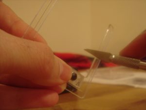
The next step was to go over all the edges with a sharp hobby knife to remove any plastic burrs. There were only a few, but it’s important to remove them as they can interfere with bonding the pieces together later in assembly.
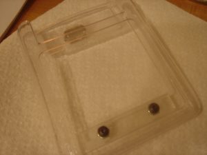
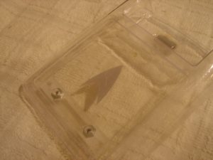
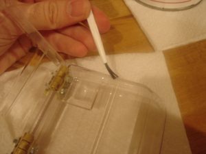
I then attached the door support frame. There are scribed lines on the frame, which line up very nicely to opening for the door, so aligning this piece is very easy. Making sure the supplied screws were facing outward, I then attached the support frame to the body with some Weld-On #3 acrylic adhesive. Now I’m fairly new to Weld-On, but it only took a few applications to get used to it. I used a small brush to apply the solvent. Just make sure you attach the pieces quickly and hold them together for a few seconds. You should be able to see where the bonding occurs.
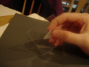
While I was waiting for the support frame to dry, I sanded down the edges of the door to remove any excess material from the rounded corners.
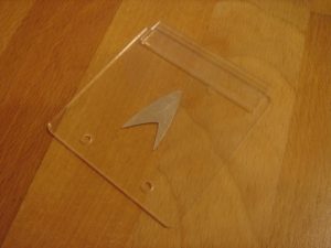
Once the door was ready, I gave it a quick test fit to make sure it fit properly on the support frame on the back of the main body (Make sure to put the Rodd.com decal on the access panel toward the inside of the body). Looks good! I then temporarily attached the door using the two supplied 4-40 button-head screws.
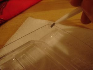
Be sure to do the following on a firm, flat surface. I took the supplied acrylic tab and used its scribed line to align it to the inside of the top of the door opening. I then used a small amount of Weld-On to tack the tab to the door itself (the side of the door with the Rodd.com decal). Be careful with this step as too much adhesive will propagate through capillary action, and you could accidentally affix the door to the tricorder body, which would be bad. Once the adhesive has dried, you can remove the door and tab and apply additional adhesive to permanently attach this tab to the door. This tab will provide support for the top portion of the door (the support frame provides support for the other three sides of the opening).
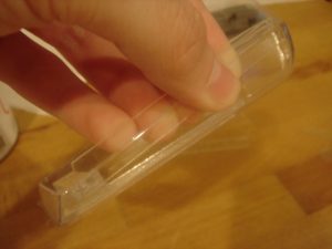
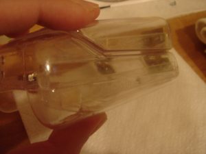
I then took the supplied acrylic cleats and cleaned all the edges with my hobby knife. These cleats will be used to provide support for the seams of the tricorder halves. Once the cleats were cleaned up, I used some more Weld-On to attach the 3.25″ long cleats to the inside of the back portion of the upper tricorder body. Be sure to align the angled edge of the cleat toward the angled end of the tricorder body. Do your best to keep 1/2 the cleat length above the tricorder half as it will provide support for the top portion of the tricorder body after the two halves are attached later. Repeat for the other side.
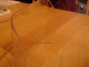
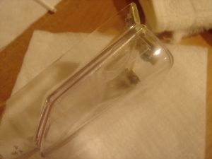
Similarly, I applied the cleats for the flip-out door. The only difference is these cleats to be flush with the edge of the back half of the flip-out door. The cleat is difficult to see in the picture since everything is clear acrylic, but these pieces will provide support for the front portion of the flip-out door.
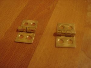
I then had to prep the hinges. I disassembled both hinges and gave them each a good sanding with 120 grit paper. This removes any coating on the hinges, which could prevent the adhesion of paint later in the build.
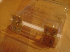
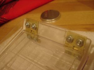
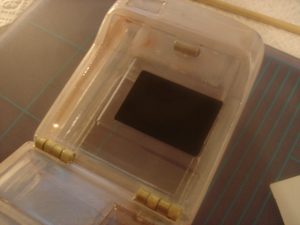
Next, I attached the hinges to the front half of the upper tricorder body. This is done by feeding the hinges through the pre-cut holes in the body. Then, two 4-40 screws and nuts are used to attach the hinges to the tricorder. I left the screws a little loose so I could properly align the flip-out door. I then took the front portion of the flip-out door, and attached it to the other half of the hinge. Be sure to use the 0.020″ thick styrene shim to provide adequate clearance between the flip-our door and body, as seen in the picture. Next, I aligned the flip-out door to body. Once completed, I tightened up all the screws.
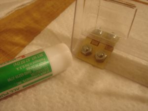
I then used some superglue to attach the nuts to the back of the hinges. Be sure not to get any of the glue on the screws, or you’ll never get them out!
Next, I installed the magnet that will be used to activate the reed switch of the electronics. I used some superglue to attach it to the front side of the flip-out door. I had to be careful not to place it too close to the upper edge of the door, otherwise the magnet for the scanner might interfere with its operation. In addition, it can’t be placed too close to the lower end of the door or it’ll attached itself to the hinges. After the magnet was installed, I loosened the 4 screws on the lower flip-out door. I then slide the back portion of the door in between the hinges and the other half of the door. I then re-tightened the screws.
I then applied some Weld-On around the edges of the flip-out door to join the two halves of the door together. Just beware that once you do this, the door is closed, so be sure to complete any work that has to be done on the internal side of the door before you seal it up. For instance, there is typically an LED that goes behind the ID decal on the door, but I have chosen to exclude this LED for my build. If you’re installing this LED, don’t forget to do so before you close up the door!
Next, I applied the cleat which goes between the two hinges on the main body section. Again, I just used some Weld-On and let it dry.
There are two, very small cleats left. Each one goes in the upper corners of the front side of the main body. Again, these cleats will act as supports when the two halves are joined together, so be sure to give them adequate drying time.
Once the cleats were dried, I then attached the two sections of the main body together. I accomplished this by gently squeezing the two halves together and running Weld-On along the seam.
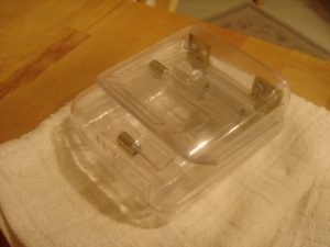
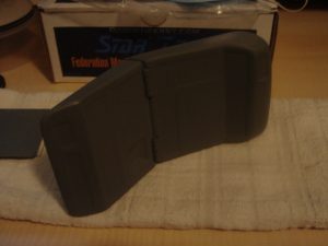
At this point, the primary components have all been assembled. In fact, I now have a clear tricorder! I have to say I’m very surprised at the ease and speed that this kits builds up. Next up will be filling the seams.
Smoothing the Bondo
January 8, 2006
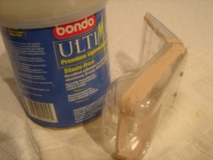
I let the kit sit for a few days to let the adhesive really dry (also, because I was too busy to get to it). I then mixed up some Bondo automotive filler and applied it to all the seams and screw heads. Be careful not to over-do it, as the Bondo takes quite a deal of sanding to remove, and any unnecessary material will be a pain to sand down. I let the Bondo cure over night. Afterwards, I gave the Bondo a good sanding with 150 grit paper. This removed any “Bondo-burrs” . I then worked my way up from 200 to 450 grit paper, which helped blend the Bondo in with the rest of the tricorder.
Puttying the Scanner
January 21, 2006
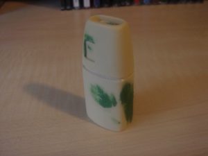
I then went over the rest of the tricorder with some automotive spot putty to fill in any additional gaps. After drying, I repeated the sanding process up to 450 grit paper. The instructions then move on to assembling the scanner. Since I’ve already done this, I decided to take care of some minor body work on the scanner. The piece has a few tiny holes that I patched with Squadron’s green putty, which is specifically designed for smaller filling smaller holes. In addition, when I glued the two pieces of the scanner together, I used just a tad too much glue, and it ended up seeping out into the recess between the two halves. I used some of my micro-files and a sharp hobby knife to remove the excess glue. Next up will be sanding the little bugger.
Splash Coat
January 22, 2006
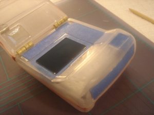
Due to some abnormal weather in my area, it was unseasonably warm, which allowed me to put a splash coat on the tricorder kit. Before I could do that I had to mask off the areas where the LEDs will shine through. Again, the advantage of using a clear body for this kit is because it alleviates having to drill out any holes for the electronics. All you need to due to mask off where the blinkies will go to prevent paint from blocking their view. First, I cut the provided mask for the main display screen from the graphics sheet. I then applied it to the outside of the tricorder body in the designated recess.
I then used some of Scotch’s blue masking tape to mask off where the additional electronics will go. For the LEDs that will be on the main face of the tricorder, I just created some simple masks to cover the general area. For the top circuit and the small recess above the main face, I used some tracing paper to create templates of the graphic decals, similar to what I did for marking the holes on the top section. I then used these templates to create masks that I applied to the kit. Also, be sure you mask the inside of the kit as well to prevent any overspray. As you can see in the picture, I stuffed a napkin inside the kit, which is a lot easier than masking off all areas.
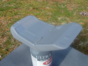
Once all the masking was done, I went outside and applied the splashcoat to both the tricorder and scanner. Again, the splashcoat is a light coat of primer that helps accentuate any blemishes that may have been missed during sanding. I used my trusty Krylon primer to apply the splashcoat. Afterwards, I inspected the kit, and applied some of Squadron’s green putty to fill any imperfections I found.
Graphics
January 29, 2006
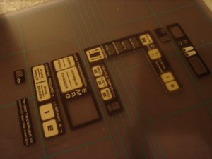
Well since the weather in my area has taken a turn for the cold and rainy, I thought I’d take care of a few odds and ends with the kit. First up, I recently ordered a graphics upgrade package specifically designed for the Mark VI with electronics. I used a sharp pair of scissors and hobby knife to trim them up. One thing to note is that this upgrade package did not include graphics for the handscanner, so I used the ones supplied with the kit. This involves applying the included contact-paper to the graphics, and then cutting them out. I used a wide putty applicator to flush out any air bubbles between the contact-paper and the graphics. I then used my scissors to cut out the graphics for the scanner. I also cut out the remaining mask, which will be used for the EMRG area of the lower door.
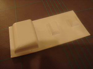
After that, I tackled, what I will refer to as, the reflector housings. These three pieces come together on a piece of plastic. They are designed to work in conjunction with the electronics to focus the light for the main viewscreen and two of the LEDs on the top array. I cut them out using my hobby knife, and then sanded them down with 150 grit paper to even out their edges and remove any burrs.
Primer
March 12, 2006
Things have been pretty busy lately, so I haven’t had much time to work on my mark vi kit. However, we recently had some unseasonably warm weather in our area, and I was lucky enough to be able to sneak the primer coat on. Again, I went back to my Krylon primer and applied three medium-to-heavy coats. I went for the heavier coat of paint this time to ensure there will be no light leaking through once the electronics are installed. After the paint dried for a day, I gave it a good wetsanding with some 800 grit paper.

