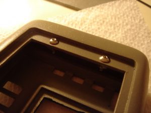
Next, I took the supplied nuts to secure the back access panel. I placed the nuts inside the main cavity and screwed them down using the included screws. I then carefully applied a bead of 5-minute epoxy around the base of the nuts to secure them to the tricorder body. Be very careful as not to epoxy the screws or else you’ll never get them out.
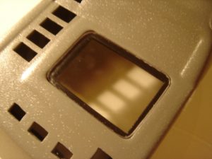
I then moved onto installing the clear plastic piece that would serve as the display screen. While I had sanded down the piece for a tight fit prior, the additional thickness of the coats of paint required some additional work to get the piece to fit in the recess. However, the final fit was so tight that this piece didn’t require any additional adhesive.
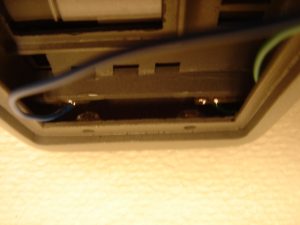
Onto the fun part; it was time to attach the lower flip-out door to the main body. By inserting the hinges into their respective cut-outs, you can use some epoxy or hot glue to affix the hinges to the inner portion of the main body. Be extra careful not to get any adhesive on the hinges otherwise you might go through what I did. I used some epoxy that ended up dripping down over the hinges, rendering them useless. After I pried the two halves of the tricorder apart, I had to tear the hinges off the door. This required the installation of a new set of hinges (including more Bondo, sanding, painting, etc). After I got the new hinges installed and started painting, I noticed the styrene sheet used to close the access panel of the lower door was coming loose. I discovered that during the process of wetsanding the newly installed hinges, water had leaked into the cavity of the lower door through the hole drilled out for the ID LED. The moisture, combined with the heat from outside, weakened the epoxy I used to attach the door. This required that I reattach the door, Bondo, sand, paint, etc….AGAIN. So be very careful when attaching the hinges. And if rework is required, be sure to seal the LED hole with some masking tape.
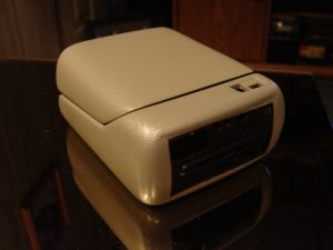
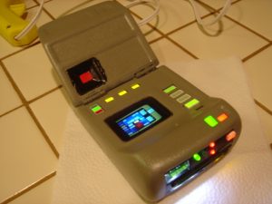
So after all that, I finally go the lower door and main body put together!
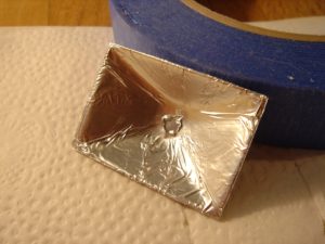
Next, I moved onto installing the “bucket” part of the display screen. This bucket will serve to back-light the film cell used as the display. I used some spray adhesive and tin foil to make sure the inner portion of the “bucket” was very reflective so the light from the LED would be more effective in lighting the film cell.
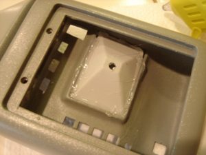
I then placed the pre-cut film cell with diffusion sheet into the recess of the main body. I carefully installed the “bucket” portion on top and held it down firmly to hold the film cell in proper alignment. I then ran a bead of low-temperature hot-glue around the “bucket’s” edge to secure it in place.
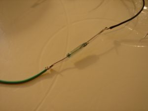
Moving onto the electronics, I soldered the magnetic reed switch I prepared earlier in series with the positive terminal of the battery. When installed in the location I tested before, the magnet will be engaged, causing the switch to be an open circuit. With the switch open, the battery is disconnected from the electronics, and the tricorder will be off, which is what I want. When the door is opened, the magnet is disengaged, the switch becomes a short circuit, connecting the battery to the electronics, and the circuit boards are powered on.
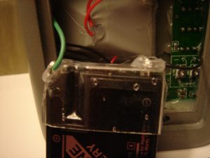
The kit comes with a vacu-formed piece of plastic to hold the J-type battery that powers the electronics. I found it needed a little help to get the wires to make proper contact with the battery terminals. (Basically, I had all the electronics installed only to find out they didn’t work. I spent a couple hours un-installing them only to find out the battery wasn’t making contact with the leads!) I tied the leads from the circuit boards around two spare screws I had laying around the house. I then installed these screws into the battery holder with some low-temp hot glue.
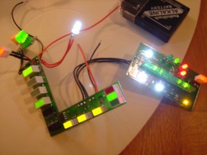
With the battery holder completed I gave the electronics a quick check to make sure they were working properly. Ooo, blinkies!
I moved onto installing the electronics into the main body. Again, I used the low-temp hot-glue as it secures the boards in place very well, but it will not damage the resin body or electronic boards. In addition, if anything does go wrong, the glue can be removed with a little isopropyl alcohol. And it’s cheap! After the boards were installed I gave everything a quick check to make sure everything was still operating and to ensure my reed switch was in the right place.

