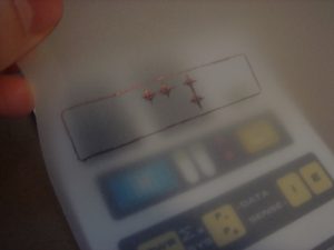
Next step is to drill the holes for the 4 protruding LEDs on the top of the tricorder. To accomplish this, I first checked to make sure the graphics were properly aligned with the LEDs on the circuit board. Once I did that, I used some tracing paper to create a template of the graphic decal that goes on the top portion of the tricorder. I marked the center locations of the 4 LEDs that will stick through the tricorder body. I also outlined the decal itself so I could properly orient it on the tricorder itself.
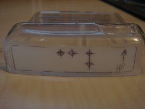
I then aligned the template in the recess of the tricorder body for the top graphic. I used some Scotch tape to hold the template in place. Note the “Up” note on the tape, which I added to make sure I didn’t put the template on upside down.
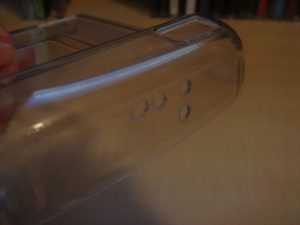
I then used a punch to mark the center of each LED hole. Be sure to use something stiff to back the tricorder when doing this step, as the plastic is very flexible, and using a punch without supporting the material could damage the kit. I then used a 1/8″ drill bit to drill each of the 4 holes. Afterwards, I used a sharp hobby knife to remove the plastic burrs. Last, I gave the circuit board a quick test fit to make sure the LEDs were lined up properly.


